


A sealed oil-immersed transformer is not simply a tank with the lid bolted down. On the 35 kV S9 line the word covers three separate pieces of hardware. There is a corrugated tank wall that absorbs the oil's expansion, a vacuum filling process that leaves no air behind, and a protection set that watches oil temperature and pressure.
Each of the three removes something from the maintenance list, and each is visible on the drawing rather than in the sales text. A transformer manufacturer in china is judged on parts like these, because the tank, the fill and the protection set are all built in-house. The S9 line runs from 800 to 31,500 kVA at 35 kV or 38.5 kV, with low voltage at 3.15, 6.3 or 10.5 kV. The same construction questions apply whether the unit feeds a small plant or a substation.
THE TANK DOES TWO JOBS
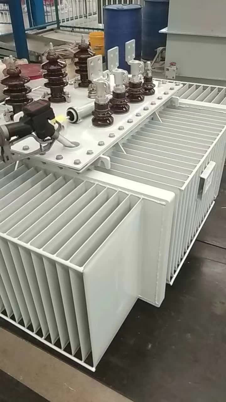
The tank wall is corrugated rather than plain, and the corrugations are not decoration. They add cooling surface to the oil, and they flex as the oil volume changes with temperature. That flexing is what takes the place of a breathing volume, so the oil is not pushed out to atmosphere every time the unit warms up.
The wall is powder coated after forming, and the panels are reinforced with a film. A corrugated wall is thinner than a plain plate of the same strength, so the handling and the coating both matter more than they do on a flat tank.
Two things follow for the site. The unit arrives with a fixed footprint, listed in the dimension table below, so the plinth and the cable trench can be built before it lands. And the wall is the part most likely to be damaged in transit, which is why the export packing is called out separately from the electrical specification.
WHAT THE VACUUM FILL REMOVES
Oil is drawn into the tank under vacuum, not poured in at atmospheric pressure. The vacuum pulls moisture out of the insulation before the oil goes in, and it leaves no air pocket behind afterwards.
That matters for two failure modes. Moisture lowers the dielectric strength of the insulation, and oxygen in the oil accelerates ageing. A sealed unit that is filled this way starts with neither, and it keeps the oil away from air for as long as the tank stays sealed.
Fluid choice sits outside the tank design. The shift towards ester fluids changes how the oil ages and what it does if it leaks, while the vacuum fill and the sealed wall work the same way with either fluid.
The seal is only as good as its fittings. That is why pressure testing is worth asking about on a sealed design, and why a leak shows up first as a gas reading rather than as a visible stain. The method used to find those leaks is total gas pressure measurement, and it is worth knowing before the first service visit.
THE PROTECTION SET, RATING BY RATING
Every rating on the line carries a pressure relief valve. It is the last line of defence: if internal pressure rises faster than the tank can take, the valve opens and the tank survives.
A gas relay with alarm and trip terminals is available on request. The relay catches the slow faults, the ones that produce gas before they produce heat, and it is the reason oil-filled units can be monitored rather than simply inspected.
Both devices only pay off if someone reads them, and maintenance practice for oil-filled units is built around that routine.
Temperature is read through a pocket welded to the tank top, with the sensing bulb sitting 120 ± 10 mm into the oil. Units from 1,000 to 2,000 kVA also carry an outdoor signal thermometer, which puts a readable dial on the tank instead of a probe point for a handheld instrument.
Monitoring has moved past the dial. Digital sensors now put oil and winding temperatures into a plant system, which turns a monthly walk-round into a trend line.
For a buyer, the practical question is which of these are standard and which are options. The relief valve is standard across the line. The gas relay is not, and a specification that assumes it will be fitted without saying so is a specification that will be corrected at the drawing stage.
THE DATA LADDER, 800 TO 31,500 kVA
| Rating | No-load loss | Load loss | No-load current | Impedance | Oil weight | Gross weight |
|---|---|---|---|---|---|---|
| 800 kVA | 1.23 kW | 9.90 kW | 1.0 % | 6.5 % | 790 kg | 3,040 kg |
| 2,000 kVA | 2.72 kW | 19.35 kW | 0.7 % | 6.5 % | 1,195 kg | 5,345 kg |
| 6,300 kVA | 6.56 kW | 36.90 kW | 0.48 % | 7 % | 2,200 kg | 11,300 kg |
| 20,000 kVA | 18.00 kW | 83.70 kW | 0.40 % | 8 % | 6,060 kg | 29,700 kg |
| 31,500 kVA | 26.28 kW | 118.80 kW | 0.32 % | 8 % | 6,890 kg | 40,300 kg |
Read down the capacity column and the ratios move in a way that surprises first-time buyers. Capacity from 800 to 31,500 kVA is about 39 times larger, while no-load loss grows about 21 times and load loss about 12 times. The larger unit is more efficient per kVA, which is why the loss figures cannot be compared across ratings without dividing by capacity.
Impedance steps as the rating climbs: 6.5 % up to 2,500 kVA, 7 % from 3,150 to 6,300 kVA, 7.5 % from 8,000 to 16,000 kVA, and 8 % from 20,000 kVA upward. That step matters at the design stage, because it sets the fault current the switchgear has to interrupt.
No-load current falls from 1.0 % at 800 kVA to 0.32 % at 31,500 kVA. That figure matters when the unit sits on a long feeder, because it is the current the line carries with the plant switched off.
Oil weight is the figure that decides the bund. From 790 kg at 800 kVA to 6,890 kg at 31,500 kVA, it is roughly 17 % of gross weight at both ends of the table. A containment volume sized on the dry weight rather than the oil weight will be wrong at every rating.
FOOTPRINT, AND WHY THE RAIL SPACING MATTERS
| Rating | L | W | H | C1 | C2 |
|---|---|---|---|---|---|
| 800 kVA | 2,140 mm | 1,320 mm | 2,120 mm | 820 mm | 820 mm |
| 2,000 kVA | 2,700 mm | 1,400 mm | 2,300 mm | 1,070 mm | 1,070 mm |
| 6,300 kVA | 2,960 mm | 2,800 mm | 3,080 mm | 1,475 mm | 1,475 mm |
| 20,000 kVA | 3,950 mm | 3,450 mm | 3,850 mm | 1,475 mm | 1,475 mm |
The rail spacing is given twice, as C1 and C2, because the unit sits on two sets of wheels or rails in the length direction. In this table the two values are equal at every rating, which simplifies the plinth: one rail gauge serves both ends.
Height is the figure that catches people out in a retrofit. Height runs from 2,120 mm at 800 kVA to 3,850 mm at 20,000 kVA. A door that cleared the old unit may not clear the new one, and the bushings on the cover add to whatever the drawing already says.
WHAT THE ORDER HAS TO STATE
Six fields carry the specification: model, rated capacity, HV and LV rated voltages with the HV tapping range, number of phases, frequency, and vector group. The tapping range on this line is ±5 % or ±2 × 2.5 %, and the tap switch sits on the tank cover, so changing taps means cutting the supply first.
The vector group is not a field to leave to the supplier. The table lists Yd11 on the smaller ratings and YNd11 on the largest, and the difference decides how the neutral is earthed on the high-voltage side.
Two site conditions travel with the order as well. The installation altitude is limited to 1,000 m, and the ambient range is −40 °C to +40 °C. A site outside either figure needs that declared at the enquiry rather than discovered at commissioning.
Packing is standard export, shipped through Shanghai or Ningbo. Both are ordinary ports for this class of equipment, and both are worth naming in the order so the packing specification matches the route.
WHERE THIS SITS IN THE LINE
The 35 kV sealed range runs from S9 to S22, and the 35 kV oil-immersed page lists the ratings that are built. Where a room cannot take oil, the dry-type equivalent covers the same voltage class, and the incoming breaker is set against the impedance figure in the table above.
A sealed unit also carries less service risk on a remote site, which is where grid resilience planning starts.
A transformer manufacturer in china that builds both the oil line and the dry line can quote them against one specification, which is why the two pages sit next to each other here. Sealing a 35 kV tank changes three things on site. The tank absorbs its own oil expansion, the vacuum fill keeps moisture and air out of the insulation, and the protection set turns a slow fault into an alarm. The rest is a data table, and the data table is where the specification is won or lost.
XIAOPAI manufactures the S9 to S22 35 kV sealed oil-immersed line at its plant in Wenzhou, Zhejiang. Figures in this article are the published values for the S9 35 kV line. The ratings run from 800 to 31,500 kVA, with HV at 35 or 38.5 kV, ±5 % or ±2 × 2.5 % tapping, and LV at 3.15, 6.3 or 10.5 kV. Configuration and commercial terms are confirmed per project.


